BrandNewNoise | DIY Looper Recording Gadget Kit Instructions
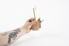
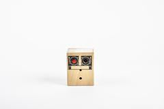
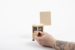
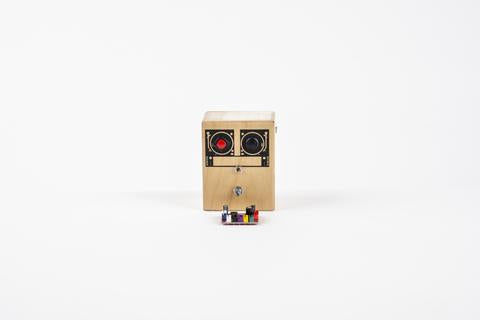
This fun DIY lo-fi Looper recording gadget is perfect for STEM kids, musicians, and tinkerers. A great DYI craft project you can make in under an hour. Here are the instructions for the DIY Kit. Purchase the kit here.
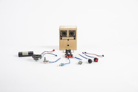
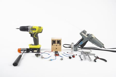
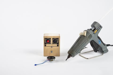
Things you will need to assemble:
- Phillips head screw driver (#5 if possible)
- Needle nose pliers
- Adjustable wrench and rubber mallet (not necessary but helpful)
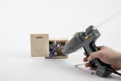
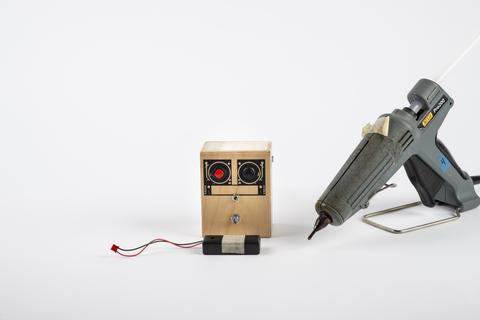
- Hot glue gun
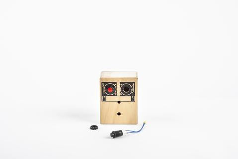
- - Screen printed wooden box
- - Microphone (Black connector)
- - Red Record button (Purple connector)
- - Black Playback button (Yellow connector)
- - Output Jack (Three prong white connector)
- - Loop Switch (Green connector)
- - Pitch Control Pot (Two prong white connector)
- - Speaker (Blue connector)
- - Battery pack (Red connector)
- - Circuit board
- - Three 5/8” screws
- - Push on knob
WARNING :
- Use caution while building. Glue guns are extremely hot! Not for children under 9 years old.
- Adult supervision strongly encouraged. Small parts. Keep away from small children.
- Step by Step Instructions
- Follow these steps IN ORDER.
- Plug in hot glue gun so that it has time to heat up.
- Place box with graphic facing you, the side with all the hole on top
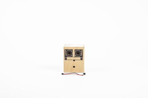
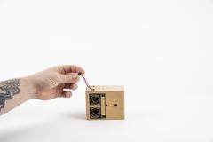
- Thread microphone wires through the larger hole
- With your hands, your rubber mallet, or another tool of your choosing gently push or tap the microphone until flush with the side
- Thread microphone wires through the larger hole
- With your hands, your rubber mallet, or another tool of your choosing gently push or tap the microphone until flush with the side
Install the Record Button:

- Place the box on its back, graphic on top
- Remove the plastic nut from the Red Record button
- Thread button wires through the left hole on graphic
- Angle the silver terminals on button to match photo
- Tighten plastic nut down to secure button
- Place the box on its back, graphic on top
- Remove the plastic nut from Black Playback button
- Thread the button wires though right hole on graphic
- Use the plastic nut to fasten the button to the unit
- Remove the plastic nut from Black Playback button
- Thread the button wires though right hole on graphic
- Use the plastic nut to fasten the button to the unit
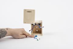
- Place the box graphic down with the back open
- Find square recess on side panel
- Remove the silver nut from the Output Jack
- Insert the Output Jack into square recess, green circuit board facing UP
- With your hands, tighten nut to secure Output Jack
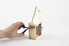
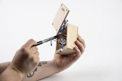
- Needle nose pliers to gently tighten the nut completely
- Find square recess on side panel
- Remove the silver nut from the Output Jack
- Insert the Output Jack into square recess, green circuit board facing UP
- With your hands, tighten nut to secure Output Jack
- Needle nose pliers to gently tighten the nut completely
- Place the box standing up, graphic facing away from you with the back open
- Remove the silver nut from the Loop Switch
- Insert the Loop Switch into rectangular recess in center, wires must be on the LEFT.
- Face graphic towards you, and thread the nut onto the switch
- Tighten the nut with wrench until secure
- Remove the silver nut from the Loop Switch
- Insert the Loop Switch into rectangular recess in center, wires must be on the LEFT.
- Face graphic towards you, and thread the nut onto the switch
- Tighten the nut with wrench until secure
- Place box standing up, graphic facing away from you with the back open
- Remove silver nut from Pitch Control Pot
- Insert Pitch Control Pot into the corresponding recessed hole
- Turn the box graphic facing you
- Thread the nut onto the pot
- Tighten the nut with wrench until secure
- Remove silver nut from Pitch Control Pot
- Insert Pitch Control Pot into the corresponding recessed hole
- Turn the box graphic facing you
- Thread the nut onto the pot
- Tighten the nut with wrench until secure
- Here you will need your hot glue gun
- Place box on side, microphone and output facing DOWN, graphic facing away with the back open
- Insert Speaker into large recess on side panel
- Make sure that the wires are facing AWAY from the graphic
- Apply a bead of glue on either side of the Speaker and on the side opposite of the wires
- Place box on side, microphone and output facing DOWN, graphic facing away with the back open
- Insert Speaker into large recess on side panel
- Make sure that the wires are facing AWAY from the graphic
- Apply a bead of glue on either side of the Speaker and on the side opposite of the wires
Install the Battery Pack
- You will need your hot glue gun for this
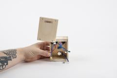
- Place box upright, graphic facing away from you with the back open
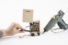
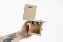
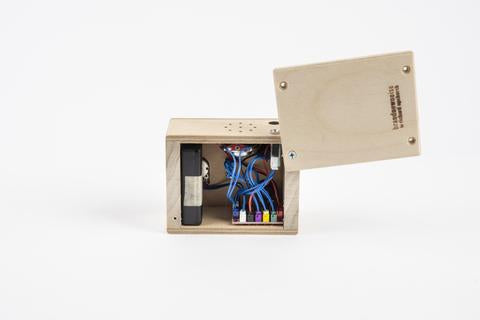
- Rearrange all wires already inside the box away from the bottom of the unit. You will want a clear space on the bottom surface to glue your Battery Pack
- Hold the Battery Pack with the wires out of the way and the tape facing down. You are now
looking at the BOTTOM of the battery pack
- Apply a bead of glue to the bottom of the battery pack
- Place the glued Battery Pack with wires facing toward the LEFT and the opposite side flush
against the RIGHT side of the box
against the RIGHT side of the box
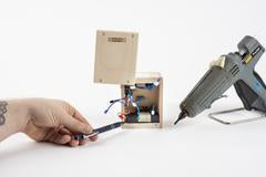
- Make sure there is clearance for the back panel to close
- Apply downward pressure until the pack is secure
- You will need the hot glue gun for this but not immediately
- Place box on it’s side, microphone, output and speaker facing UP, graphic facing AWAY from
you, with the back open
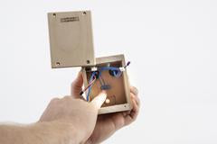
- On your circuit board locate the RED three-pronged socket
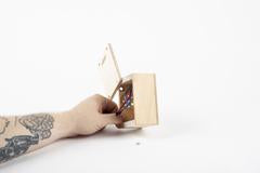
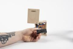
- Plug the Battery Pack connector into the corresponding RED three-pronged socket
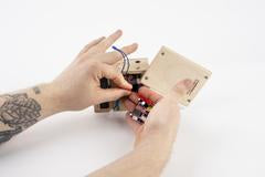
- Rearranged all other wires so that the space on the bottom RIGHT is clear
- Insert the circuit board into the space on the bottom RIGHT corner, with red sockets tight against the RIGHT side
- Make sure circuit board is clear of the metal button terminals
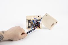
- Make sure there is clearance for the back panel to close
- Apply downward pressure until the board is secure
- Each socket on your Circuit board is color coordinated with a connector on each component that
you have just installed on your box. You will use this color coding to plug each component into
its appropriate socket on your circuit board so that you can start having fun with your box as
soon as possible!
- Each connector has a small ridge. Each socket has a slot. Align the ridge to the slot before
connecting.
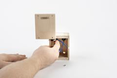
- Starting with the GREEN socket, locate the wire connected to the loop switch with the GREEN connector

- Line up the connector with the socket and apply downward pressure, you should feel it lock in
- Repeat this process with each component, plugging their connector into the corresponding, matching socket on the circuit board
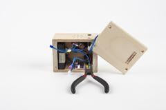
- The two-pronged red socket will remain unused
- Once all of the connectors are plugged into their corresponding sockets, take some time to make sure that they are all firmly locked in
Testing Your Voice Recorder:
- Congratulations on making it this far! Your new toy is just moments away from being complete!
- To ensure that you have the highest quality of recoding moving forward, you are going to
“cycle” through some empty recordings a few times
- Make sure that the LOOP switch is flipped to the right (this will turn the loop function off)
- Hold down the RED record button for 3 seconds
- Press the BLACK playback button
- Repeat the last two steps twice more
- Once you have “cycled” through three times, hold down the RED record button and speak into
the microphone how proud you are that you have built a functioning voice recorder.
- Press the BLACK playback button. If you hear yourself telling you that you what a great job you
did, then it is time to close up the box and add the Knob

Closing the Box:
- Place the box in it’s upright position facing AWAY from you
- Rearrange all of the wires so that you can close the back panel without catching or pinching any wires
- Locate the three 5/8” screws
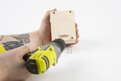
- Using your Phillips head screw driver, drive the screws into the existing holes on the back panel of the box
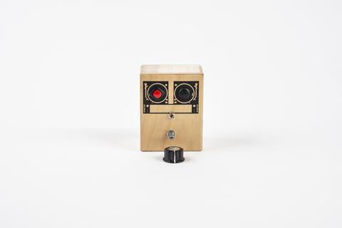
Adding the Knob
- Turn the box so that it is facing you. It looks pretty good so far, doesn’t it? One more step and you’re ready for endless recording and looping fun!
- Make sure that the Tone Knob is turned all the way to the left
- Holding your knob, arrange the white line on the knob to match the diagonal position of the pot

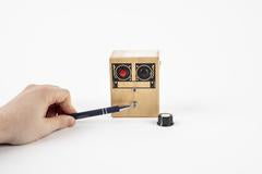
- Apply forward pressure to the knob
- Once it is securely on, turn it back and forth a few times to make sure that it is smooth
Now that your box is complete, tell it a joke while holding down the RED record button. Press the BLACK
playback button, flip the LOOP switch to the left, and turn the knob back and forth. Now you’re listening to a joke being told by a tiny chipmunk or a huge giant. Have fun and stay weird!

